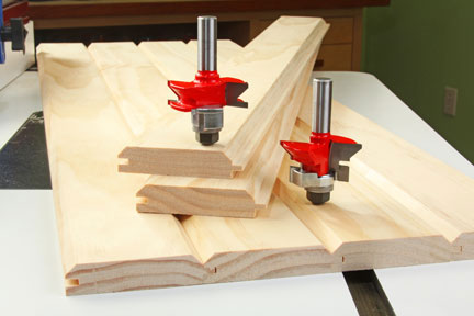
V-groove paneling or wainscot is easy to make with a tongue-and-groove bit set on the router table.
When done intentionally and tastefully, V-groove paneling or wainscot can give a dining room, den or home theater the warm, inviting charm of solid wood. You could buy it pre-milled at the home center, but your choices will be limited, and it can be expensive. Or, you can use the tongue-and-groove “V” Panel Bit Set shown here (Freud stock number 99-191) to make it yourself. Just think: custom paneling or wainscot using anything from paint-grade poplar to purpleheart, and you control the quality!
Be aware that these are large, heavy bits designed to be used on a router table only. They will shape the entire edge of a workpiece and do not have pilot bearings to limit cutting depth. You’ll need a sturdy fence to provide the necessary workpiece support, preferably with facings that can be closed up around the cutters. Here’s how to set up and use these bits effectively for your next wall treatment project.
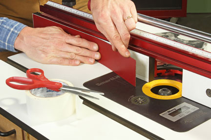
Step 1: Since these bits remove all of the contact surface of a workpiece during routing, you’ll need to account for that situation when setting up the router table fence. The solution is to apply a shim to the outfeed (left) side of the fence, then register the bit against the amount of offset this shim provides. A piece of plastic laminate, fixed in place with double-sided tape, works well (see Photo 1).
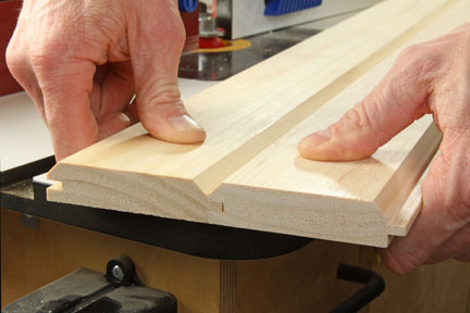
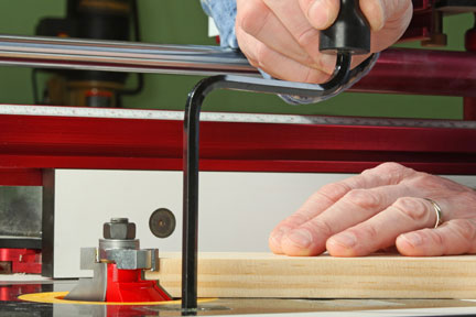
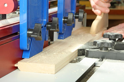
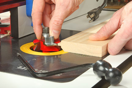
Step 2: In the opening photo above, notice that the right-hand bit cuts a thin tongue and half of the “V” bevel profile. The left bit creates a mirror-image groove and the other half of the “V” profile. You can use them in either order; we’ll start with the tongue cutter. Install the bit in your router table, and raise it above the table until the portion that cuts the tongue is centered on your workpiece thickness. It’s helpful to set a piece of scrap on the table and against the bit to visualize the cut it will make (see Photo 2). By raising or lowering the bit, you will increase or decrease the size of the “V” you will make as well as shift the tongue’s position.
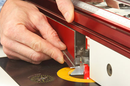
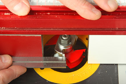
Step 3: Move your router table fence over the bit, and adjust the fence facings as close to the cutting edges as possible to minimize tearout. Use a straightedge to align the end of the tongue with the shimmed side of the fence (see Photo 3). The cutter should barely graze the straightedge when you rotate the bit by hand. This way, the bit will remove the laminate’s thickness from the workpiece edge on the infeed side, and the outfeed shim will support the tongue as the cut proceeds.
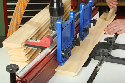
Step 4: Attach a pair of featherboards to the fence, one on each side of the bit, to press your paneling stock down firmly against the table. Clamp a third featherboard to the table in front of the bit to push workpieces against the fence. Test your setup on a piece of scrap stock that matches the thickness and width of the paneling you are making. If the test cut looks good, cut a tongue on one edge of all of your paneling material (see Photo 4). Note: Arrange the stock so the best faces are down on the table during routing.
Step 5: Once all of the tongues are milled, remove the tongue-cutter and install the grooving bit. Raise or lower it until the thin grooving portion of the cutters lines up evenly with the tongue on one of the workpieces you just routed (see Photo 5).
Step 6: Position the fence around the grooving bit so you can establish the projection of the cutters. Hold a straightedge against the shimmed side of the fence as you did before. This time, adjust the fence in or out so the straightedge meets the top, flat portion of the cutter — it forms the shoulder area behind the groove on the completed profile (see Photo 6). Lock the fence, and re-install the three featherboards.
Step 7: Try your groove-cutting setup on another piece of scrap. Fit this test piece together with one of the tongue workpieces. The back faces of both parts should be flush when the joint is assembled. If they don’t line up, you’ll need to adjust the groove cutter slightly up or down, cut a fresh test piece and try the fit again. Once the sample joint fits correctly, go ahead and mill the groove profiles (see Photo 7). Don’t forget to arrange the paneling face-down again so the “groove-side” V-bevel will also be cut into the show faces.
Step 8: If you were careful with your routing procedure, you should now have tongue-and-groove paneling that’s ready for sanding, finishing and installation (see Photo 8).