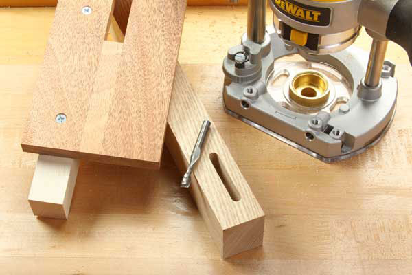
How to cut mortises accurately with a hand-held router, a straight bit, a template guide and a few scraps.
There are many ways to make mortises — and just about as many tool options. A plunge router is one of the best choices, because you can accurately control the depth of cut, and the machine delivers clean and precise results. Here’s a simple, dedicated jig you can make quickly for cutting mortises of a specific dimension with your plunge router. Its top plate has a slot to fit a template guide mounted to the router, so cutting accuracy is assured. And, a fence attached beneath the jig’s top plate provides a stout clamping surface for your workpiece, whether you secure the jig and workpiece in a bench vise or with hand clamps. Here’s how to make and use the jig.
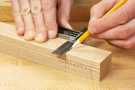
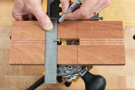
Step 1: Since this mortising jig is dedicated to a specific-size mortise, laying out your mortised workpiece is the first step in building the jig. Everything follows from the mortise proportions. Mark the length and width of your intended mortise with a square, and extend layout lines a short distance onto the adjacent (un-mortised) faces of the workpiece to serve as reference lines later (see Photo 1).
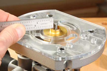
Step 2: A second important piece of information you’ll need is the outside diameter (O.D.) of the screw-in template guide you’ll use in your router with this jig, as well as the diameter of the appropriate router bit. Here we’re going to use a 5/8-in. O.D. template guide around a 1/4-in. carbide spiral upcut bit. (Note: a conventional two-flute straight bit would also work fine.) The difference between the template guide’s O.D. and the router bit diameter is called the offset. You can measure it (see Photo 2), but a more accurate method to find offset is to simply subtract the bit diameter from the template guide O.D. — in our case, 5/8-in. minus 1/4-in. equals 3/8-in. of total offset. Divide this number in half to find the offset on either side of the bit; in this example, it is 3/16-in.
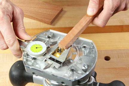
Step 3: For the top plate of your jig, choose a piece of 1/2-in.-thick scrap that measures 4- to 6-in. wide and about 10- to 12-in. long. Rip a strip from one edge that is exactly as wide as your template guide’s O.D. or slightly wider (see Photo 3). The strip won’t work for the jig if it is any narrower than the template guide — it establishes the width of the jig’s slot.
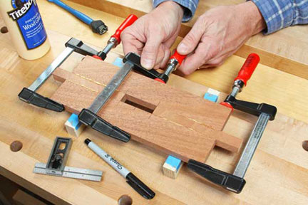
Step 4: Now rip the top plate of your jig in half, and crosscut the spacer strip in two. Measure the length of your mortise layout from Step 1, and add to its length the total amount of offset (in our case, 3/8-in.). This number determines the total length of the jig slot. Mark the slot locations on your top plate workpieces; centering the slot on the top plate is a good idea. Form a “sandwich” of top plate pieces and spacer strips — spread open to the overall slot length — to create the jig slot. Glue and clamp the top plate assembly together (see Photo 4). When the glue dries, trim off the excess spacer strips from the ends of the plate.
Step 5: With the template guide and router bit installed in your plunge router, turn the router bottom-side up and fit the template guide’s bushing inside the jig’s slot. Plunge the router base until the bit passes through the plate so you can access it as a reference for measuring. Now use a combination square to mark long layout lines on the plate that indicate the width of the mortise. Then slide the bushing from one end of the slot to the other to mark the length of the mortise. When marking the plate, always reference from the outside edge of the router bit (see Photo 5).
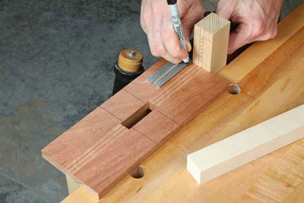
Photo 6
Step 6: At this point, you can install the jig’s fence. To locate the fence’s position on the top plate, align the mortise “width” layout lines on your workpiece with the corresponding lines you just drew on the top plate. Draw a short layout mark on each end of the plate that’s even with the edge of your workpiece to set the fence location. You can position these layout marks either to the left or the right of the jig slot; it doesn’t matter. A bench vise can be helpful for holding the mortised workpiece steady as you align it with the plate for marking (see Photo 6).
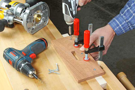
Step 7: Select a piece of scrap several inches longer than your jig’s top plate to use for a fence. Clamp it beneath the top plate, aligned with the layout marks you drew in Step 6. Fasten the parts together with countersunk wood screws (see Photo 7). The extra fence length on each end of the plate can be helpful for clamping purposes.
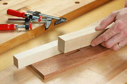
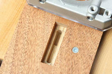
Step 8: The short reference lines you drew onto the un-mortised sides of your workpiece will now come in handy for positioning it in the jig to prepare for routing (see Photo 8). Clamp the workpiece and jig together securely.
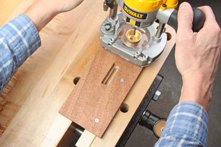
Step 9: Use the stepped turret on the router base to set up the first and subsequent depth cuts to excavate the mortise depth you need (see Photo 9). With each pass, you can either push or pull the router along the slot to clear the waste — the feed direction doesn’t matter. Make sure to remove no more than about 1/8-in. of material with each pass, especially when routing hardwood (see Photo 10, below). Use compressed air or a shop vac to keep the mortise area and jig slot clean.