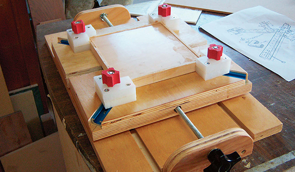
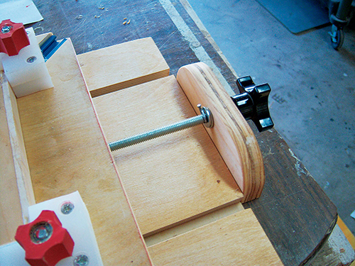
I make a lot of small-sized frames, and this clamping jig makes gluing them a snap. It consists of a base with two sliding panels secured by a key slot guide to the base.I used mostly scrap wood I had on hand, except for a few pieces of hardware. The HDPE plastic corner braces cushion the corners, and excess wood glue just peels off after glue-up. The clamping pressure is applied by two 5/16″ threaded rods run through 5/16″ inserts in the sliding panels. The 5/16″ rods are epoxied into the female knobs. Add a cotter key and washer to the inside of the end stops to give you two-way movement of the panels. I didn’t have 1″-thick HDPE plastic on hand, so I just screwed together two 1/2″-thick pieces. The notches in the corner braces are 3/4″ deep.
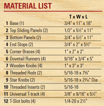
My hold-down knobs for the corner braces are shop-made on the drill press and band saw. I happened to have a couple of 5/16″ star knobs on hand, but these could also be shop-made. The dimensions of this jig are fine for my purposes but can be easily adjusted to meet individual needs. Having the sliding panels secured to the base by two dovetailed runners keeps them properly aligned in use. I put paste wax on the runners so they will glide easily. The threaded rod arrangement holds the clamping pressure in place without any additional clamps or stops. To make the two sliding panels, lay out and machine the various grooves, holes and slots as shown in the Drawings.
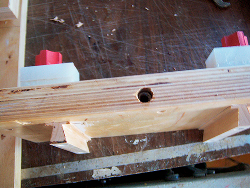
On the threaded rods, the 1/8″ hole for the cotter key (you can substitute a small finishing nail) is approximately 1″ in from the base of the knob. (You can take up any slack with a washer or two.) Measure the depth of the knob you’re using before mounting the rod in the knob, and drill a through hole for the pin using a V-block to hold the rod in position.
I used a 5/8″ dovetail bit to cut the shaped slots in the base. The dovetailed runners are made using the same size bit on the router table with the material held vertical against the fence. (See the Drawings.) For safety, use at least a 3″-wide piece of 3/4″ maple and use a featherboard to keep the material firmly against your router fence as you make your cuts. Sneak up on the cuts for the runners until you have a snug but not too tight fit. (Test your setup on scrap wood.)
Once you have the final tweaks for the runners, you can make them in two passes by using a single 24″-long piece of hard maple, then slice off the runners at the table saw, and cut the four runners to length.
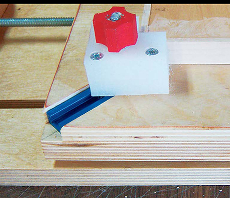
NOTE: To ease attachment of the runners to the sliding panels you’ll want to leave a “base” on the runners. Use a piece of carpet tape on the runners, place them in the base slots and align your sliding platforms, then press them in place. With the runners held to the sliding platforms with the tape, remove the assembly from the base, then countersink and install two screws to each runner.
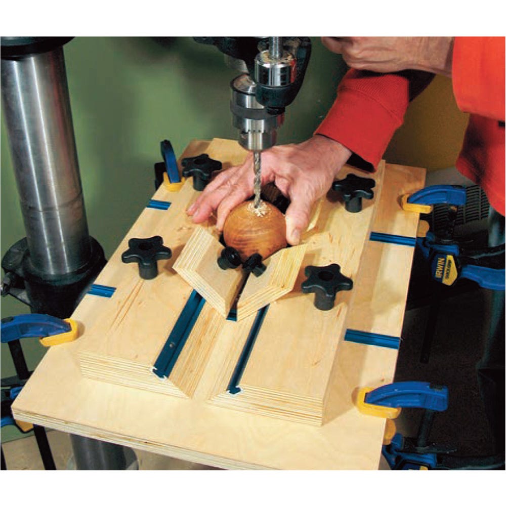
Shop-made Knobs
I chose to make my own knobs for the corner braces, because I wanted them narrow enough so they would not interfere with any frame components 1″ or more thick. To make my knobs, I started with a 3″ x 3″ piece of hard maple, then marked the center of the piece (see the Drawings). Mark four holes 5/8″ from the center and drill four 3/4″ holes completely through the stock. To accept the nut, I drilled a 15/32″ hole at the center, 1/4″ deep. Then I drilled a 1/4″ hole through the middle of the knob. Trim away the excess scrap on the band saw or scroll saw and sand any rough edges. Put a small amount of epoxy in the 15/32″ hole and, with the nut screwed into the end of a hex bolt, tap the nut into place with a hammer until it’s fully seated. When the epoxy dries, you’re ready to paint if you wish, then mount them to the corner braces using T-bolts. Go ahead and do the final assembly of all the pieces — and now you are ready to get busy with clamping up some frames!
Click Here to download a PDF of the related drawings.
Hard to Find Hardware
5/16”-18 Threaded Inserts (2) #28811
Universal T-Track 3′ (1) #26420
Star Knobs (2) #54589
T-Slot Bolts (4) #37295
– Raymond LaRochelle lives in California, where he serves as the president of the Viet Nam Veterans of Diablo Valley.