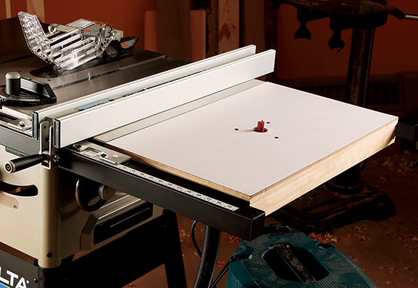
Customize your table saw by replacing one wing with this convenient and floor-saving router table. It features a unique internal dust collection system for cleaner operation.
By Bill Wells
Most table saws come with an extension wing on the right-hand side of the saw table. Replacing this wing with a router table is an excellent modification to your saw. It is convenient, saves valuable floor space, and it’s inexpensive to build. When I decided to add a table-mounted router to my small shop, adding it as an extension to my saw was my best option. I also wanted effective dust control, but none of the commercially available dust control systems appealed to me. So I decided to design my own.
The concept I came up with is a dust collection system built right into the tabletop itself. An internal chamber connects the router bit opening on the top surface with a shop vacuum connection on the bottom. Dust and chips are vacuumed away down the bit opening as soon as they are cut.
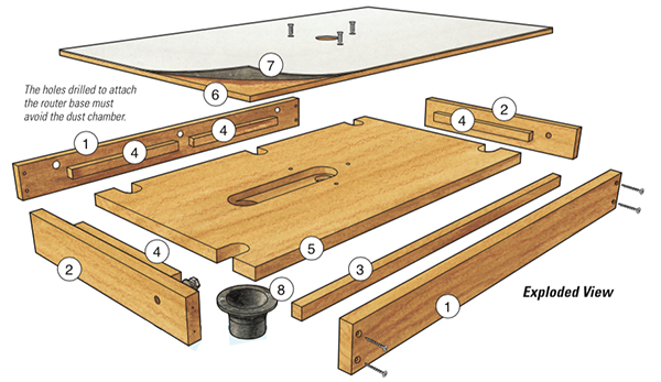
The table is made in three layers: a top surface of durable countertop laminate, a middle layer of 1/4″ MDF and a bottom layer that includes the dust conveying chamber, made of 3/4″ birch plywood. There’s no special fence with vacuum openings and no hoses on the table.
Careful Measurements Come First
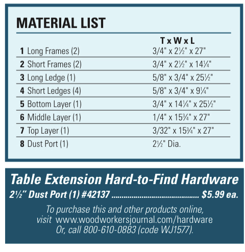
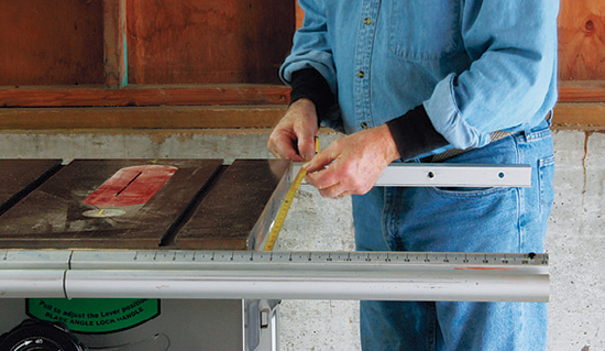
Remove the extension wing of your saw and determine the size of your new router table extension. The most critical dimension is the width — the distance between saw fence rails; mine was 271⁄8″.The depth of the extension is somewhat arbitrary. I chose mine to extend to the end of the fence rails, which on my saw is 161⁄2″. If you want an even deeper table, you can extend a bit farther, but no more than about 6″ past the end of the rails.
Building the Frame
Bolting your completed extension to the saw can be the trickiest part of the proj- ect. So build the frame first; that way you can deal with unique mounting require- ments and interferences from the get-go.
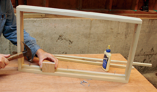
Build the frame from 1×4 solid wood to the dimensions determined in the previous step. The width is critical; the frame should fit snugly between the saw rails. Butt-joint the frame pieces using 2″ screws and yellow glue. Then add a ledge inside the frame to support the top; this ledge should be at a depth equal to the thickness of the bottom plywood layer. I used a piece of 3/4″ scrap as a gauge.
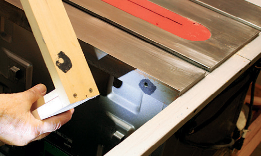
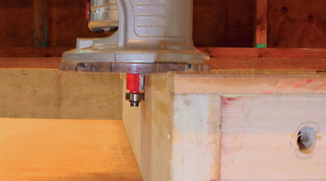
Now fit the frame into position on the saw. Since the middle and top layers will rest on top of the frame, set the top of the frame about 5/16″ lower than the cast- iron saw surface and mark this location. Then mark the location of the bolt holes for attaching the frame to the saw table.
I dabbed black paint around the bolt holes, then pressed the frame against the top. The transferred paint clearly shows the hole location on the wood frame.
Drill these holes and elongate them, and all others, for later height adjustment. Now bolt the frame to the fence rails. You may not be able to use the original fasteners that came with the saw. Leave the frame in place for now; you will be making minor adjustments to subsequent components for access to the fasteners you just installed. Better to do these now than later!
Making the Bottom Layer
This layer fits inside the frame, so measure the inside dimensions and cut a piece of 3/4″ birch plywood to fit. Go ahead and set this plywood panel into the frame.
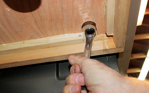
Looking from below, you will see that the plywood has likely blocked access to the fasteners. Mark the location of all fasteners, and turn the plywood layer over. You can now cut away small areas of plywood so that you have room to get a wrench onto the bolt heads. I used a 1-1⁄4″ hole saw and hand saw. Don’t worry about the holes you have left in the plywood; there will be a sheet of MDF covering this area. Place the plywood back into the frame and check your wrench access to the fasteners.
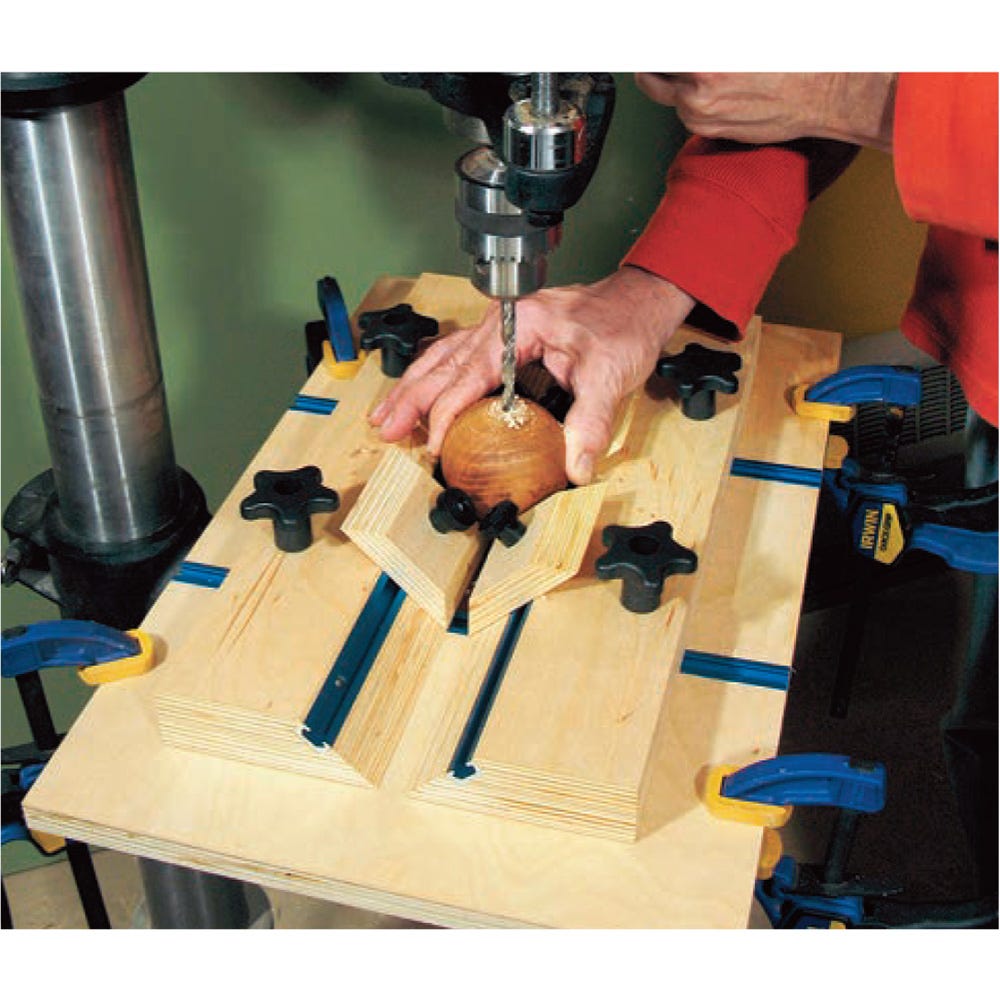
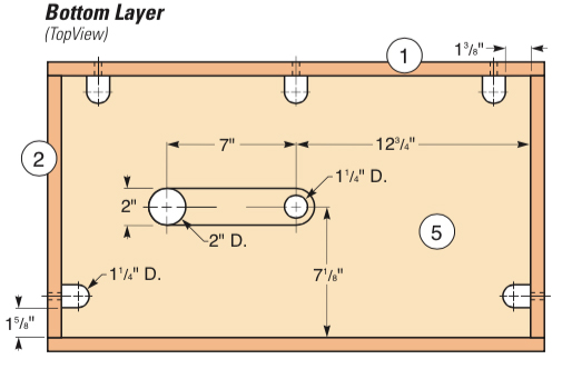
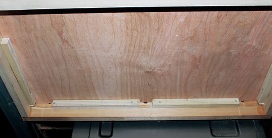
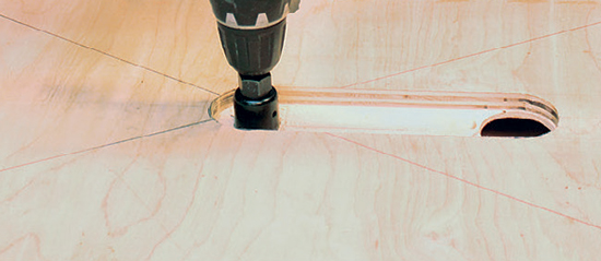
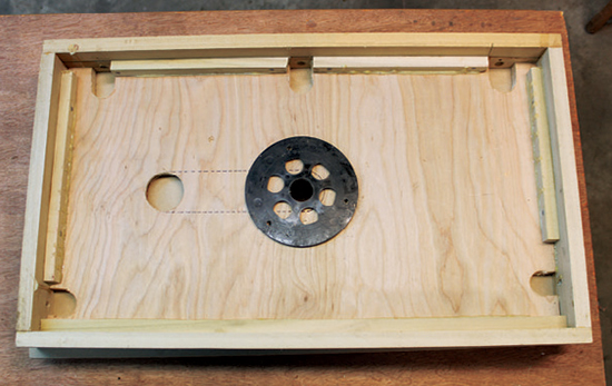
Next, it’s time to rout a recess in the top of the plywood layer that will become the internal dust conveying chamber and to drill a hole for the vacuum connection. Assuming you will be connecting the vacuum hose from the back of the saw, the routed recess and drilled hole will look like the photo at left. Note the diagonal cross lines that mark the table’s center point.
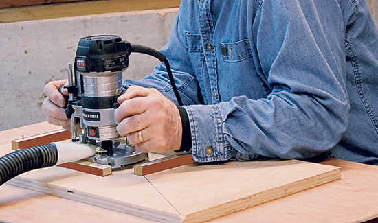
Rout a 1/2″-deep recess as shown in the drawing, then drill the 2″-diameter vacuum outlet hole with a hole saw. I tacked four temporary guides to the plywood to help me rout the rectangular portion of the recess, then routed the rounded ends freehand.
The diameter for the bottom bit opening will depend upon the size of your router’s collet. Measure the largest diameter of the collet; the bit opening in the plywood layer should be slightly larger, but not more than about 1/8″. My collet measured slightly less than 1-1⁄4″, so I drilled the bit opening at the center with a 1-1⁄4″ hole saw. I drew crossed lines on all layers to mark center points.
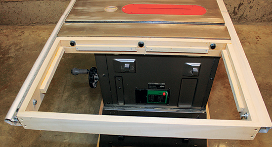
With the frame still in the saw, dry-fit the plywood into the frame. The plywood should be flush with the top of the frame, with the vacuum outlet oriented to the back side of the saw. Remove the frame.
Moving Up to the Middle and Top
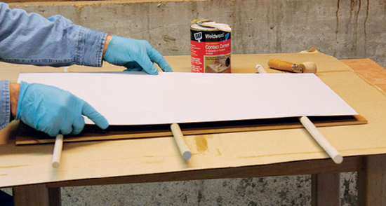
As I said earlier, the middle MDF layer and top laminate layer sit on top of the frame. Cut them both oversized to begin with — you’ll trim them down later. Mea- sure the outside dimensions of the frame and add an inch to that length and width, so that there will be 1/2″ overhang on all sides of the frame. Using contact cement and a roller, glue the laminate work surface onto the MDF layer. Once the layers are bonded together, use a 1-1⁄2″ hole saw to drill the top bit opening at the center of the combined laminate/MDF layer.]
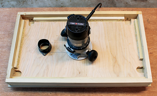
The next step is to glue the top layers onto the plywood bottom layer. It is critical to position the top bit opening directly over the bottom bit opening in the plywood layer. To do this, I first chucked a bit into the router I intended to install under the table; placed the router, bit up, on a work table; and then set the frame and plywood assembly onto the router. This way, I could position the top work surface layer so that the bit opening was concentric with the router bit. Once the layers are in correct arrangement, clamp them together and remove the router. Now carefully mark the position, and glue the top layer to the plywood layer. Avoid getting glue in the vacuum chamber area. When you clamp the layers together, be sure they don’t slip out of position! After the glue dries, fit the layers into the frame, with the vacuum outlet positioned toward the back. Now glue them into the frame, and clamp.
Trim and Complete the Table
There are a few tasks left to complete before bolting the table to the saw. First, trim the laminate and MDF with a flush- trim bit and file or sand the sharp edges smooth. Next, turn the table over and place the router over the bit opening.
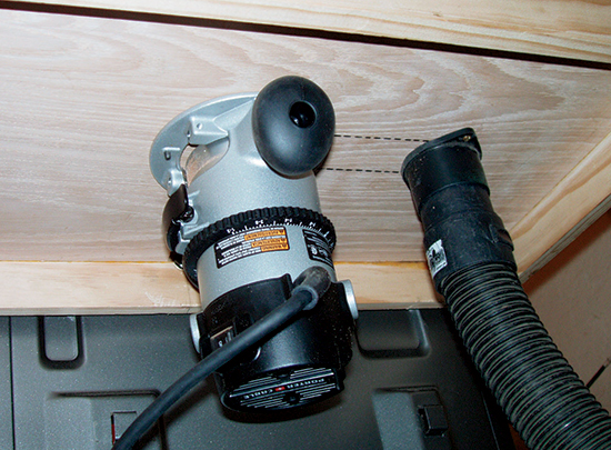
This is the time to decide how you want the router positioned, in order to reach the On/Off switch easily and to provide access to the motor clamping mechanism in the router base. After deciding these details, you can drill the holes for the router mounting screws. There are two im- portant issues here: 1) the holes must not go through the internal chamber, and 2) the router must be positioned so that the bit is dead center in the top bit opening. A good way to mark the screw locations is to use the router’s subbase as a template. After the holes are drilled, turn the table back over and countersink the holes. I mounted my router with flathead socket head screws. Now attach the 21⁄2″ dust port connection, and the table is done.
Bolting the Table to the Saw
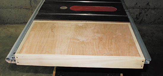
Since you built the frame to fit your specific saw, and you provided access to the mounting bolts, this step should be pretty easy. When you get the table loosely attached, place a straightedge on the table surface of the saw, and check that it is level and well aligned. You may have to ream out a bolt hole or two in the frame to get the router table flush and level with the saw table. Then bolt the project tightly in place on the saw. With that, you’re finished building this project. Now you’re ready to put it into service by making some test cuts! I hope your new router table is as convenient and dust-free as mine has turned out to be.
Bill Wells is a frequent provider of workshop tricks to Woodworker’s Journal.