This article, “Turn a Ship’s Wheel Clock,” is from the pages of American Woodturner and is brought to you by the America Association of Woodturners (AAW) in partnership with Woodworker’s Journal.
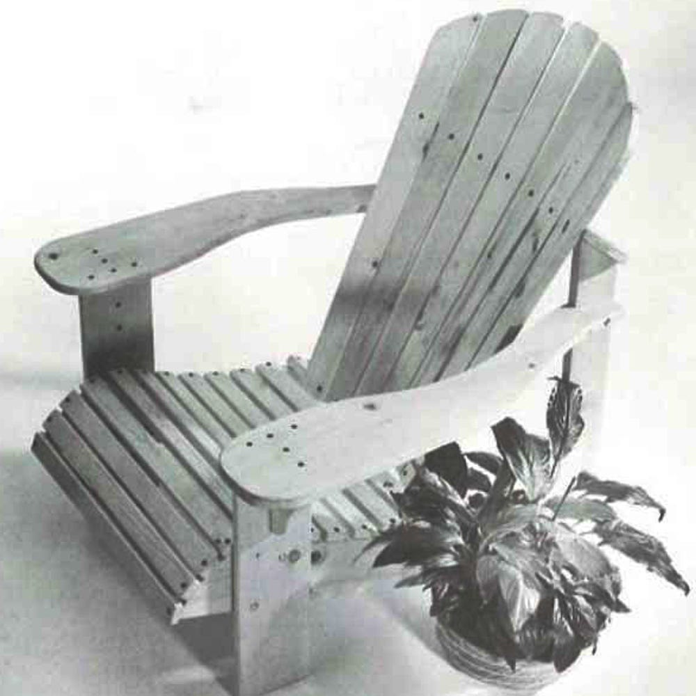
Living just outside of Homer, Alaska — “halibut fishing capital of the world” — and being an avid fisher myself, I suppose it’s not surprising that I like to create things with a nautical theme. I recently made a couple of ship’s wheel clocks, a project that combines spindle turning and segmenting. The clocks were interesting to design and make, and I thought the process I went through was worth passing along to other turners.
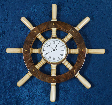
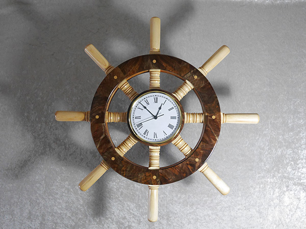
The first thing I did was search the Internet for images of ship wheels. Some have six spokes, some have eight, some even have ten. I decided I liked eight spokes. The clocks I made have a central hub 6-1/2″ (17cm) in diameter, an outer wheel 15″ (38cm) in diameter, and an overall diameter, to the tips of the spokes, of 23-1/2″ (60cm).
Spokes and Spacers
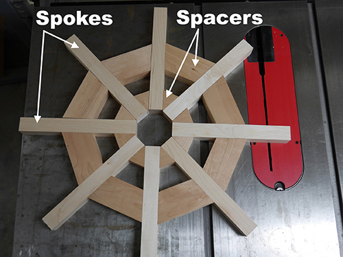
Almost any combination of hardwoods would work well for this project. I chose maple for the spindles and cherry for the spacers in the hub and wheel. A layer of walnut covers the hub and wheel.
First, I cut and planed the spindle, or spoke, stock. I made the spindles 1-1/4″ (32mm) square and about 10-1/4″ (26cm) long. Since I didn’t have 1-1/4″-thick stock, I laminated the pieces using thinner material, which worked out fine. I made a couple extra spindles, one to practice my spoke design on and another in case I had a major blooper when turning.
I used a simple formula to determine how long my spacers needed to be for the 6-1/2″ hub and the 15″ wheel. If you subtract the width of all the spindles from the circumference of each circle, you’ll be left with the total spacer length. Divide that total by eight (because there are eight spacers) to arrive at the length of each spacer.
πd – (8 × 1-1/4″) / 8
This means the spacers for the inner hub would measure 1.3″ (or about 1-5/16″) long, and the spacers for the wheel would measure 4.6″ (or about 4-5/8″) long. The spacers in the outer wheel are 2-1/2″ (6cm) wide, and the spacers in the hub are 1-1/4″ wide, both made from laminated stock. I made the hub and wheel slightly oversized and then turned them to final diameter.
When planing the thickness of the hub and wheel spacers, I left the wood a few thousandths of an inch thicker than the spindle stock to ensure there would be room for inserting the turned spindles through the wheel and into the hub, which is one of the last steps.
I cut the angles on the spacers (and the walnut segments for the outer layers of the wheel and hub) on a table saw sled. As turners who do segmented work will know, the miter angles on the spacers and outer ring segments are determined by dividing 360 degrees (a full circle) by the number of spacers (or segments), divided by two (since there is a miter on each end). For the eight spacers between the spokes (of both the hub and wheel), the miter angles are 22.5 degrees. For the twelve segments of the outer wheel layer rings, the miter angles are 15 degrees.
Outer Layers
My next step was to fabricate the top and bottom layers to cover the spacers and spokes in the outer wheel and hub. I chose 3/8″- (9.5mm-) thick walnut. For both the hub cover, which barely shows once the 6″- (15cm-) diameter clock is installed, and the back of the outer wheel, I used plain walnut. For the more visible segmented pieces on the front of the wheel, I used figured walnut.
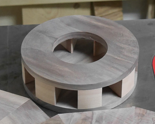
Hub
I placed a piece of masking tape on either side of the still-square spindles and used them as guides for clamping and gluing the spacers to the back of the hub. The masking tape ensured that the turned spokes would fit into their slots without a lot of persuasion. I was careful to remove any glue that squeezed out into the spaces where the spokes fit. Once the glue dried, I glued the front layer to the hub, again cleaning off any glue squeeze out. I turned a 2-1/2″-diameter recess 3/16″ (5mm) deep in the back of the hub, mounted the hub in my chuck, and turned and sanded it to shape.
At this point, it’s a good idea to turn a hole in the front of the hub to accept the clock. I purchased a 6″ “fit-up,” or friction-fit, clock from clockparts.com, thinking this type of clock would be simple to replace if needed. Fit-up clocks are available from a number of different suppliers, and they come with ivory or white faces, at least three styles of numbering, and a price range of about $20 to $25 each. The clock I bought had a 6″ face with a brass bezel and fit snugly in a 3-1/8″ (8cm) hole.
I first turned a 3″ hole in the hub and then enlarged it using a router. I turned a 3-1/8″ hole in a scrap of plywood, attached the plywood to the hub with double-sided tape, and used a pattern bit in my router to clean up and widen the hole. The pattern bit ensured that the sides of the hole would be smooth and straight (not sloped). And the template can be reused if I decide to make any more fit-up style clocks. As an alternative, you could skip the router and simply fine-tune the hole on the lathe.
Wheel
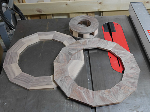
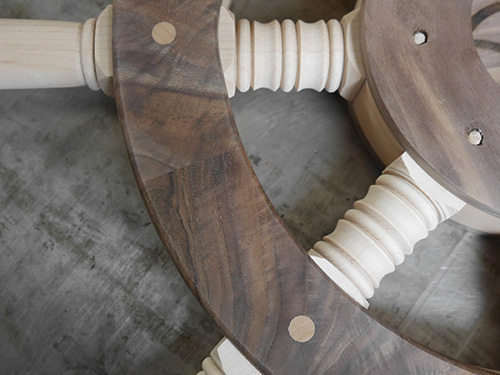
For the front and back layers of the wheel, I made rings comprising twelve segments. I used wood glue to assemble the segment rings.
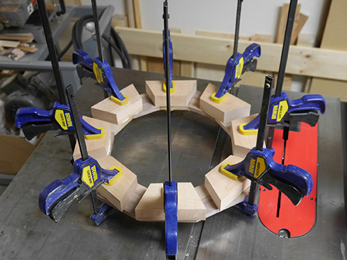
I followed the same glue-up procedure for the outer layer on the wheel as I did for the hub. When gluing the top ring of the wheel onto the spacers, I was careful not to center a segment glue joint over a spoke hole, where the wheel will later be pegged to the spoke. On my first clock, when I pounded a peg through the wheel and into a spoke at a joint line, I created a slight separation of the segmented pieces. Yikes!
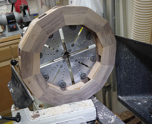
When the glue dried, I mounted the wheel on a chuck with large plate jaws to turn and sand it. The eight grippers on the jaws fit nicely in the eight slots for the spindles. I had to be careful to turn only the outer half of the wheel so as not to contact the grippers or aluminum jaws.
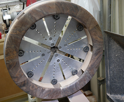
But that worked fine since I could simply reverse the ring to turn the other side. When turned and sanded, the 15″ wheel ended up having a width of about 1-7/8″ (5cm).
Turn the Spokes
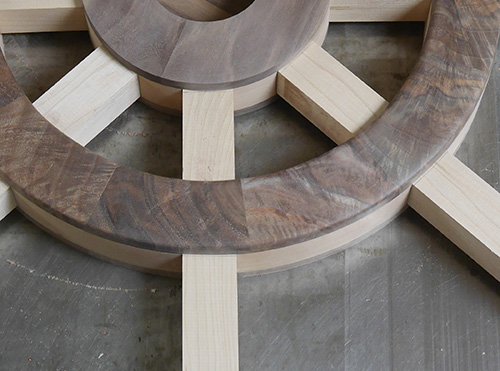
Once the hub and outer wheel were turned and sanded, I started to work on the spokes. First I inserted the still square spoke blanks through the wheel and about 1-1/4″ into the hub. Then I marked, with pencil lines, where the spokes needed to remain square.
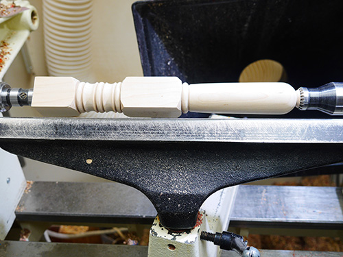
I turned and sanded the spokes between centers, first rounding the areas outside of the hub and wheel, then turning some beads and coves that I thought looked appropriate.
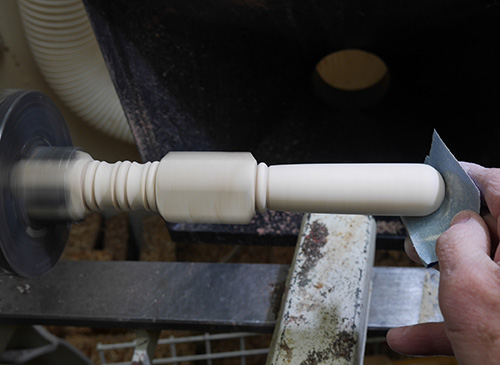
I then mounted the spokes in my spigot jaws before parting off so I could sand the handle ends without the tailstock restricting access.
Assemble and Finish
When everything was turned and sanded, I slid the spokes through the wheel and into the hub. I fastened the spokes to the hub with 1/4″- (6mm-) diameter fluted dowels, making sure to position them about 3/4″ (19mm) from the rim so they would be covered by the clock. I then turned some 3/8″-diameter maple dowels and used those to fasten the wheel to the spokes. I trimmed these plugs with a flush-cut saw and sanded everything flat.
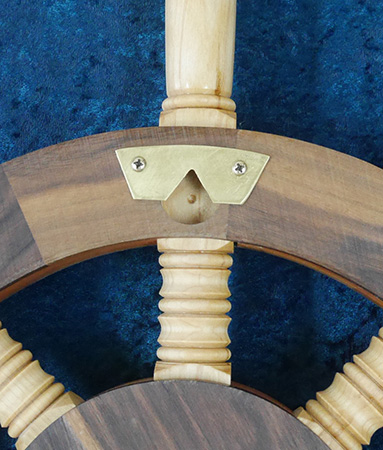
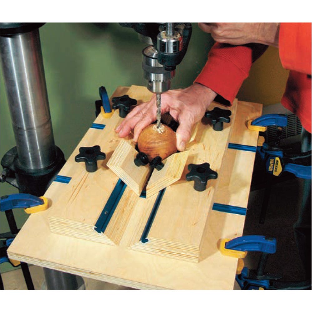
The ship’s wheel clock is pretty heavy, so to hang it, I drilled a 1-1/16″ (27mm) hole about 1/2″ (13mm) deep, centered on a spoke in the back of the wheel. Then I cut and notched a piece of 16-gauge brass and screwed it in place over the hole.
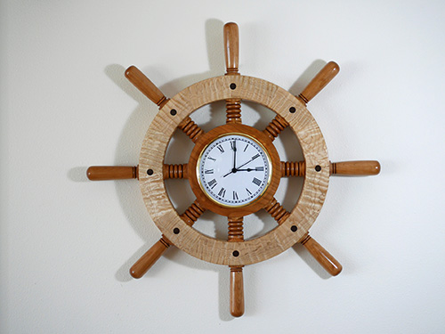
To finish the clock, Beth (my wife and business partner) put on three coats of Danish oil. After letting the Danish oil dry for three days, I put on three coats of wipe-on polyurethane, buffing between coats with 0000 steel wool. Pressing in the fit-up clock with a slight twisting motion was the final step.
Ted Heuer spent thirty years with the U.S. Fish and Wildlife Service. After retiring in 2007, he and his wife Beth moved to Kachemak City, Alaska, where they have operated a woodworking business since 2008 (tedswoodshop.com). When not making sawdust, Ted and Beth enjoy fishing, gardening, and helping to run the local artist cooperative (Ptarmigan Arts) in Homer, Alaska..