This article, “Touchless Turned Lamp,” is from the pages of American Woodturner and is brought to you by the America Association of Woodturners (AAW) in partnership with Woodworker’s Journal.
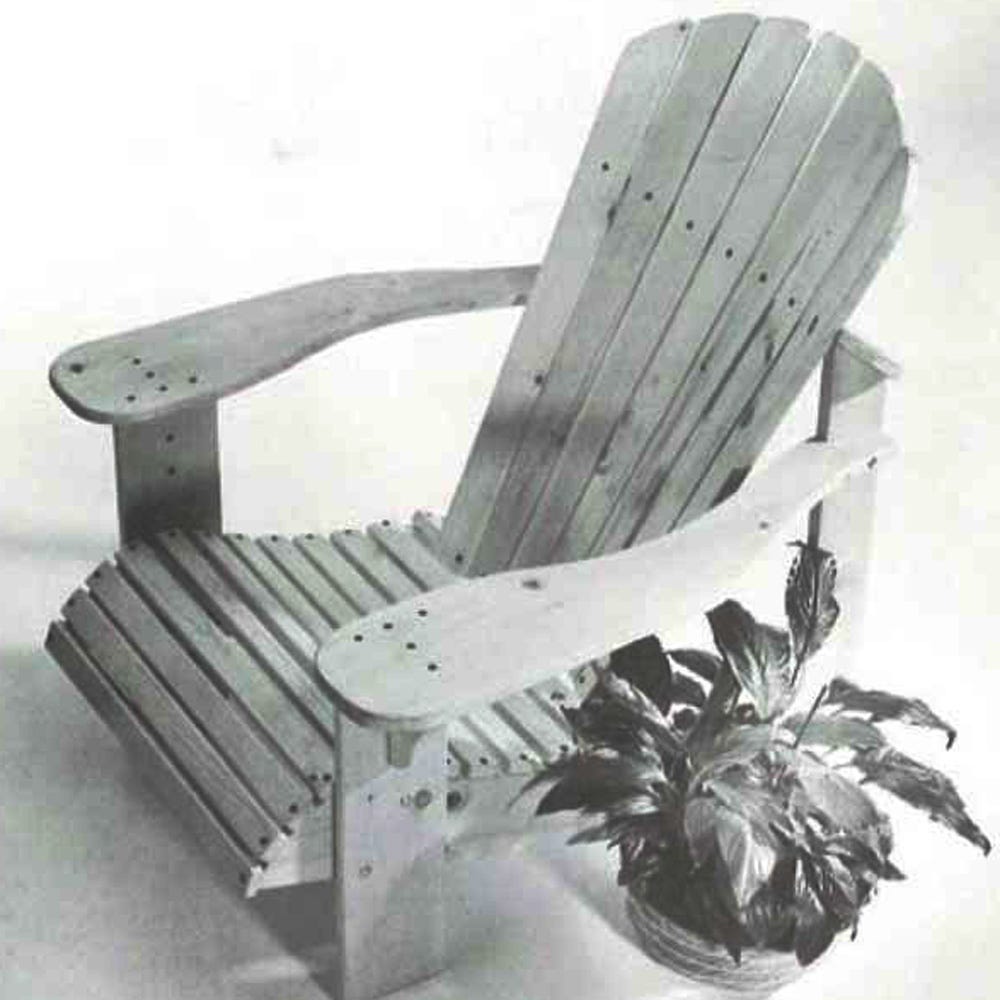
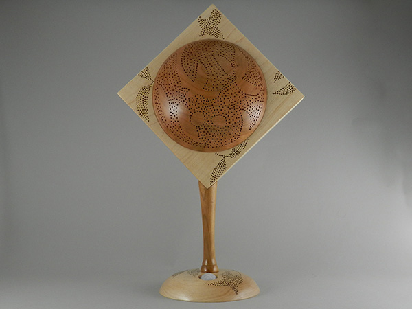
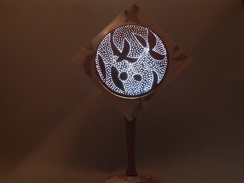
Here is a functional project with a simple but elegant design. This decorative accent lamp can be operated with just the wave of a hand, thanks to a touchless sensor protruding through a hole in its base. All wood parts can be turned from readily available 1″- (25mm-) thick stock. The design possibilities for piercing the lamp screen, allowing the light to come through, are limited only by your imagination.
Design and Materials
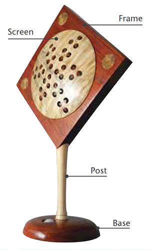
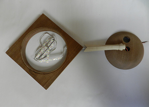
The frame holds two screens (front and back), with the front screen being pierced to allow the light to pass through. The inside of the back screen can be lined with reflective foil to increase the light’s intensity. For an attractive design, I like to make the frame and base from the same wood species, and the screens and post from another, contrasting species.
Between the two screens, a strip of LED lights is connected to the inner edge of the square frame. The turned post has a hole drilled through it, so you can connect the LED strip to the electronics, which are contained in the base. The base contains the battery pack, which needs to be accessible for replacement. With the weight of the batteries in the base, the lamp stands securely without tipping.
As outlined here, all turning for the project can be completed on a mini- or midi-lathe. The following wood components are needed, all in 1″-thick dry hardwood:
• Frame and base: Both cut from one piece, 7″ × 7″ (18cm × 18cm)
• Screens: Two pieces, 6″ × 6″ (15cm × 15cm)
• Post: One piece, 5-1/4″ (13cm) long, 1″ square
Electronics
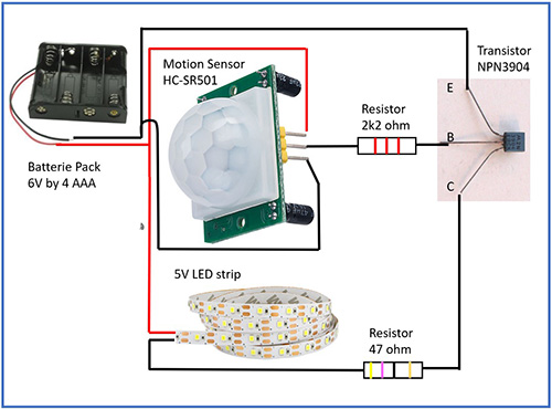
Unfortunately, I could not find a readymade kit that includes a small battery LED strip. However, the electronic parts are commonly available and can be found easily online. An example of the components and wiring is given in the photos. The electronic parts you will need include the following:
• Battery holder for four AAA batteries
• Human Infrared Sensor Module (I used HC-SR501)
• General-purpose transistor (I used N3904 TO-92 NPN)
• Heat-shrink tubing, 2mm
• DC-powered 5-volt flexible LED strip, 3′ (1m) long
• Resistors: 47 ohm, 2K2 ohm
• Soldering iron and kit, brass brush
• Electric wire stripper
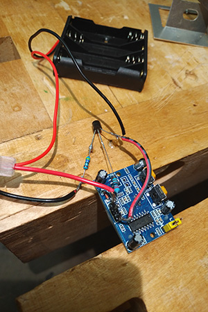
The project requires some basic soldering to make the wiring connections. If you have never tried soldering, it is not very difficult to learn, and working with low-voltage electronics is relatively safe. I provide step-by-step instructions in the video referenced at the end of this article.
Turn the Screens
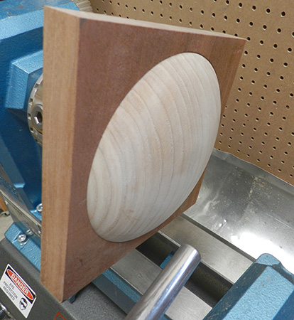
Turning the screens is like turning a simple bowl, except that the rim of the screen must fit snugly into the recess of the frame and there is no foot. To mount the screen material on the lathe, I glued sacrificial tenons, or spigots, to the center of the squares. I made the spigots the correct size to fit the jaws of my chuck.
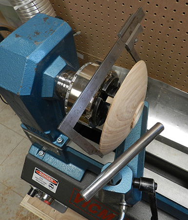
Before mounting the screens on the lathe, cut the square blanks to a 6″-diameter circle. Then, with the spigot clamped in the chuck, true up the blank and turn its outside profile to a smooth, shallow curve. Leave a small tenon to fit the jaws of your chuck.
Now reverse-mount the blank so you can turn the inside of the screen. Bring the tailstock up for support as long as you have sufficient space to turn safely. Turn a flat rim, about 1/8″ (3mm) wide. Aim for a consistent wall thickness, and continue the smooth curve down to its center, just as you would with a shallow bowl. The wall thickness depends on the type of piercing you want to do.
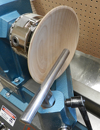
To remove the outer spigot, I reverse-mounted the screen once again, this time holding it in large plate jaws, or bowl jaws. A vacuum chuck would also work well. Turn away the temporary tenon and complete the smooth curve on the outside of the screen. If you are aiming for thin walls, you may need to temporarily take the screen out of the jaws to check wall thickness with a caliper.
After sanding the outside and with the screen still mounted, you have an opportunity to sketch a design for piercing. To function as a decorative lamp with enough light shining through, aim for at least 10 percent of the front screen to be pierced.
Repeat this turning process for the back screen, but without the piercing.
Turn the Frame and Base
Frame
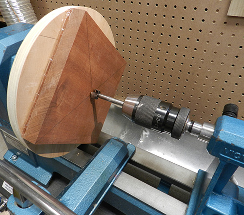
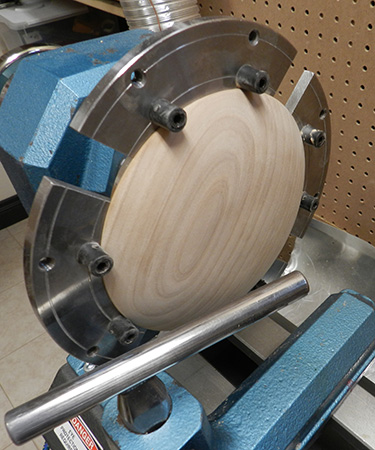
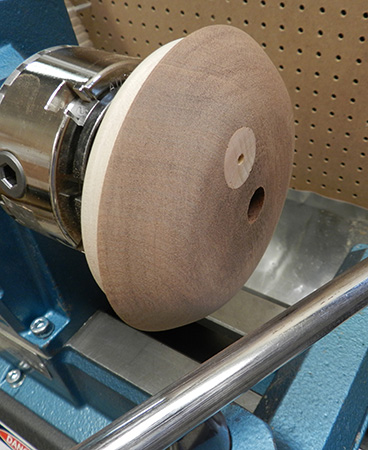
To mount the wood for the frame and base, I attached a sacrificial scrap of plywood to a faceplate. You could also mount the plywood using a chuck. Before mounting the frame, ensure the material is planed flat and cut square. I mounted the frame to the plywood disk using a seam of hot-melt glue along all four sides. Use your live center in the tailstock to help center the work.
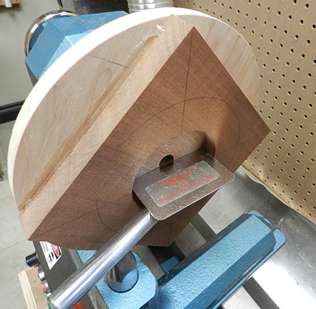
Drill a 5/8″ (16mm) hole though the center of the frame. Then widen the center area to 3-1/2″ (9cm) diameter, 5/8″ deep; this will be the cavity that will accommodate the electronic parts. You need only a parting tool and a small bowl gouge to hollow the cavity. Make sure the cavity has straight sides and a flat top.
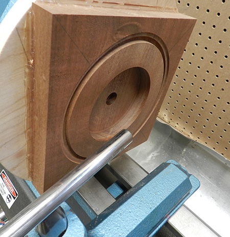
Next, cut out the 5-1/2″- (14cm-) wide base with a parting tool, carefully reducing the lathe speed just before the tool cuts through. Set the base aside. I used a parting tool to form a 1/8″-deep recess in the frame to accommodate one of the screens. Check that the screen has a snug fit in the recess.
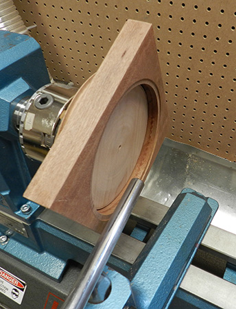
To separate the frame from the plywood disk, place the assembly in a microwave for a few seconds to melt the glue or use a heated knife to cut through it. To turn the recess on the opposite side of the frame, remount the work using a jam chuck, possibly supported by hot-melt glue.
When the frame is completely turned, mark the front and back, as well as the top and bottom corners. Any residual hot-melt glue can be removed from the frame using a heated kitchen knife or with rubbing alcohol.
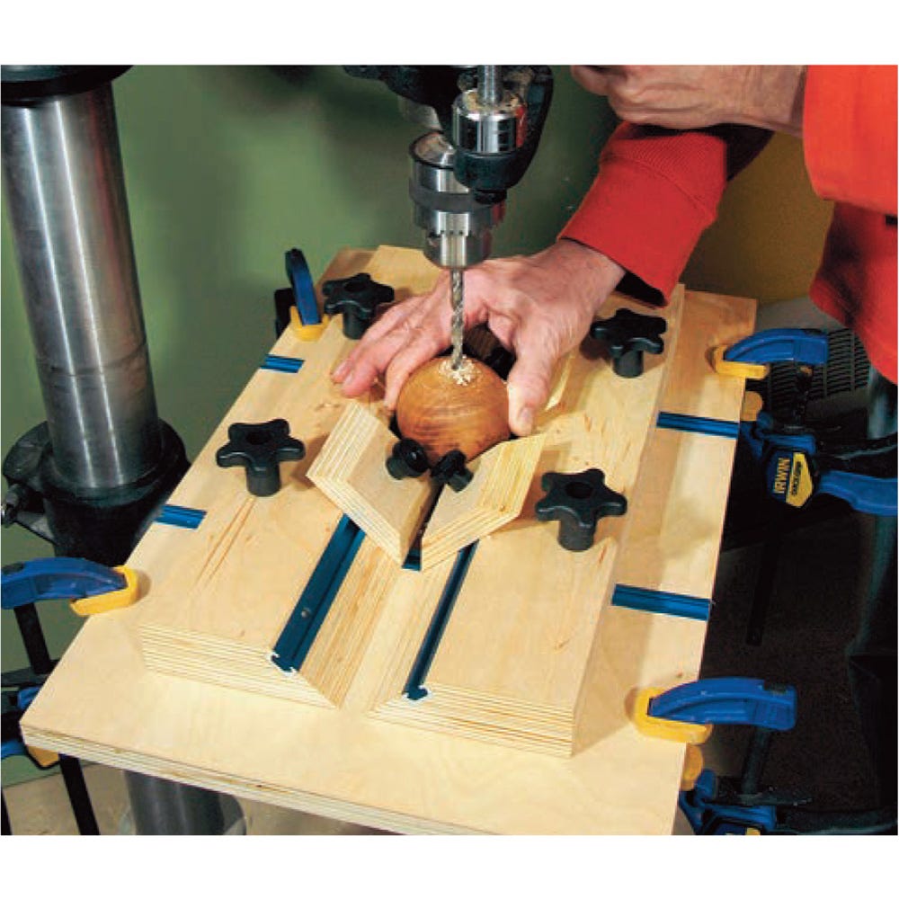
With the design of this lamp, the post connects to the bottom corner of the frame. A 3/16″ (5mm) hole is required in the bottom corner of the frame, so a cable can be passed through it and down the post. To drill this hole, I used a shopmade corner jig. The jig centers the drill bit on the corner of the frame.
Base
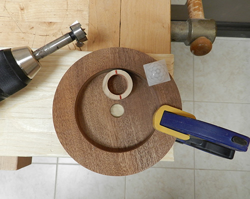
The base, which had been parted from the frame material, gets a slightly domed top. But first, drill a 7/8″ (22mm) hole through the base, up from inside the electronics cavity, about 3/16″ from its edge. Plug the drilled hole with a dowel to prevent tearout while shaping the top of the base. Any waste wood can be used for this sacrificial dowel.
I mounted the base using my chuck in expansion mode, opening the jaws into the turned recess in the bottom.
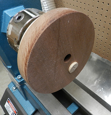
Now the top of the base is ready for turning. Pay attention to the wall thickness, particularly at the widest part of the recess, where you are more likely to break through accidentally.
A small hole in the dowel serves as a welcome guide to wall thickness. Also, check the fit of the motion sensor to decide if further turning is required. To function properly, the screen of the motion sensor needs to protrude slightly above the surface of the base.
Turn the Post
The post connects the base to the frame and serves as a conduit for an electric cable. To fit properly, the top of the post must mate with the square corner of the frame, while the bottom end must fit into the 5/8″ hole in the center of the base. A turned flange at the bottom of the post sits on top of the base.
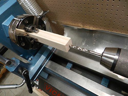
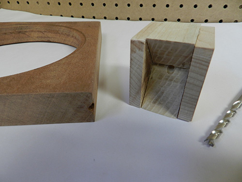
I mounted the post material in my chuck, using pen-blank type jaws, and drilled a 3/16″-diameter hole about halfway through the blank. Reverse the blank in the chuck and drill from the opposite side. This method reduces the risk of a longer drill bit drifting off center.
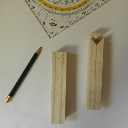
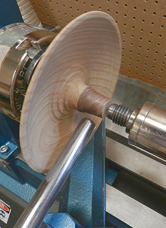
While the post is still a square blank, mark and cut out a small corner at one end, but don’t discard the cutout corner piece. Reattach the corner piece temporarily using hotmelt glue, then mount the post on the lathe between centers, with the bottom end near the tailstock.
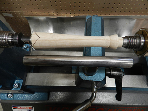
After roughing the post blank round, turn a tenon at the bottom end to fit the hole in the base. Form a flange for a seamless connection with the top of the base. Remove the post for an actual check of the tenon’s fit. Remount it between centers and shape the top end of the post, gently reducing the thickness of the two “wings” that will contact the sides of the square frame. Shape the rest of the post as you like, leaving a minimum of 7/16″ (11mm) diameter.
Assembly
Feed the LED cable through the frame, post, and base. About 3′ of LED strip will wrap around twice inside the frame. Glue the LED strip in place with spray adhesive, starting from the location of the cable hole.
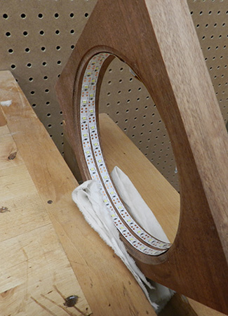
Once the available area inside the frame is covered, you can cut any extra LED strip between any two lights. This is a good time to check the function of the LEDs by temporarily connecting the strip to the battery pack. A reflective foil can be added to the inside of the back screen for improved light intensity.
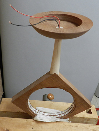
Attach the post to the base with epoxy. To glue the post to the frame, I held the frame upside down in a vise. Make sure the hole for the motion sensor points to the front of the lamp.
Check the fit of both screens before gluing them to the frame. The front screen can be glued with a few dots of hot-melt glue from the inside of the frame after the screen is pressed in place. Then add a few dots of glue on the recess and press the back screen in place.
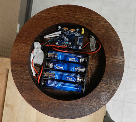
Check that the connected (soldered) electronic parts fit within the cavity of the base. With the lamp clamped upside down in the vise, put the electronics in place and connect the cable of the LED strip. After checking its function, glue the wired components in place with dots of hot melt glue. For improved stability of the lamp when standing, I covered the electronics by screwing a piece of mouse pad under the base. This will also allow access to replace the batteries.
Now it is time to give yourself a pat on the back and place the new lamp somewhere to enjoy the light when someone walks into the room!
Kai Muenzer has been an international turning demonstrator and teacher since 2012. His signature projects often combine art with function and can be viewed on his website.