This article, “Ten Principles of Clean Cutting,” by Kip Christensen, is from the pages of American Woodturner and is brought to you by the America Association of Woodturners (AAW) in partnership with Woodworker’s Journal.
Thirty-five years ago, while I was a student at Brigham Young University (BYU), I attended a woodturning demo in which Del Stubbs covered the underlying principles of clean cutting. Del explained there are universal principles that always apply to cutting material, including wood, and that we can usually trace poor results in woodturning back to the violation of one or more of these principles.
I was only able to attend the first few minutes of Del’s presentation, but over the years I compiled my own list of principles involved in getting a clean cut when woodturning. What follows is a discussion of these principles with guidance for applying them. Throughout this article, the applications are discussed mostly in relation to spindle turning but can be applied to bowl turning, as well.
Principle 1: Tool Sharpness
Sharp tools give clean cuts; dull tools do not. None of the other principles matter much if your tool isn’t sharp, so check your tool sharpness first.
Application
While I was a student at BYU, I watched Richard Raffan give a presentation on how to turn a bowl. It was an excellent demo, but what made the biggest impression on me was what he modeled about the importance of keeping a sharp tool. Richard was a production turner at the time and knew that every wasted second impacted his efficiency. He had us position a grinder near the lathe and to his left, not even a full step away from where he stood to turn. A few minutes into the demonstration, he noticed that his cutting tool had lost its keen edge, so he turned the grinder on, sharpened his tool with a quick free-hand stroke, and went back to turning without switching the grinder off. Richard left the grinder running during his entire demo and sharpened frequently. He was not content to work for even a few seconds with a dull tool.
In teaching classes and workshops, I have noticed that many people avoid sharpening their tools. They may doubt their ability to sharpen properly or may be afraid of making the tool worse. They may also be concerned with wasting precious tool steel or are simply reluctant to take time away from turning. To encourage yourself to make sharpening a priority, strive to eliminate any obstacles that make it less likely for you to sharpen your tools. Get good sharpening equipment and position it very near your lathe. Keep it free of clutter; learn how to use it.
Do not allow yourself to work with tools that have lost their keen edge. A sharp tool is a pleasure to work with and will give clean, efficient cuts. Turning with a dull tool gives poor results and can be an exercise in frustration.
Principle 2: Grain Direction
The orientation of wood grain in relation to the direction of the cut significantly impacts how wood responds to being cut. There are two key concepts here: one, wood fibers being cut should be supported by adjacent fibers, and two, sidegrain cutting should be maximized and endgrain, minimized.
Applications
It doesn’t take long for new woodworkers to discover that wood fibers unsupported by other wood fibers (or not supported in some other way) tear when being cut, leaving a rough surface. Common examples of this include tearout on the bottom side of drilled holes and “blowout” at the end of a board when planing, jointing, or routing.
Parallel Orientation
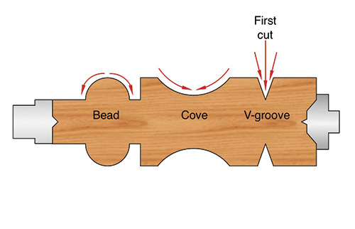
In spindle turning, with the grain running parallel to the lathe bed, it is best to cut “downhill” (from large diameter to small). You can understand this lesson by trying two contrasting approaches to cutting a cove. If a cove were cut from both sides downward toward the middle, the wood fibers being cut would be supported by fibers underneath them, resulting in a smooth surface. Conversely, if a cove were cut in one sweep, going down one side and up the other, the upward cut, from small diameter to large, would be going into endgrain fibers, which are more apt to tear when cut head-on. Also, the unsupported fibers at the very end of the cut (at the top of the cove) would tear out as the tool exits. Thus, when cutting coves, V-grooves, beads, shoulders, and tapers while spindle turning, the best results will come from cutting from large diameter to small.
Perpendicular Orientation
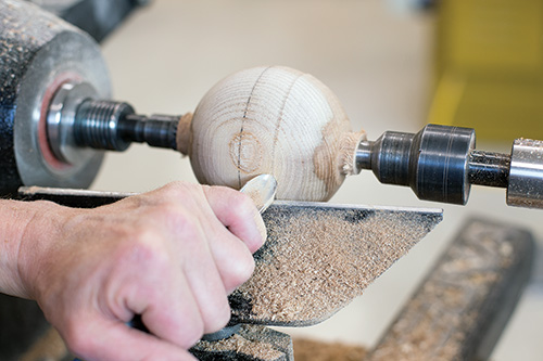
large diameter to small, on a sphere with the grain parallel to lathe bed.
Beginning turners understandably have difficulty applying this concept to workpieces mounted with the grain running perpendicular to the lathe bed. When turning a sphere, for example, the wood initially is mounted with the grain parallel to the lathe bed, allowing for clean cutting from large diameter to small.
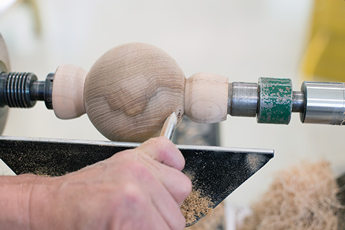
But once the sphere is roughed into shape, it is then remounted between cup chucks so the grain is perpendicular to the lathe bed. With the wood in this position, cutting from large diameter to small would violate the principle of working with the grain. To avoid cutting into endgrain, it is better to cut into sidegrain by using a shear-scraping cut and turn “uphill,” from small diameter to large.
Principle 3: Bevel Angle and Length
A more acute bevel angle on your cutting tool (with a longer bevel) will produce a finer cut than tools with a more obtuse bevel angle (with a shorter bevel). Unfortunately, longer bevels are more difficult to sharpen and require more skill to use. They are also less durable and don’t hold an edge as long. As a result, when we apply this principle, we make compromises to find a balance that will give a good cut but be practical in use.
Applications
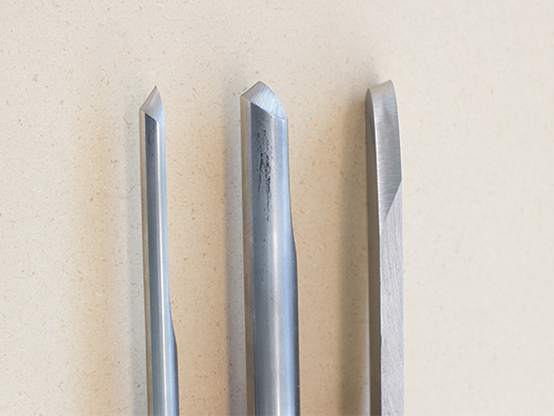
Spindle gouges are used for general wood removal as well as detail work when spindle turning. The bevels on spindle gouges are generally ground between 35° and 45°, with 40° being a good happy medium. A detail gouge is basically a spindle gouge ground with a more acute bevel angle (30° to 35°). The longer bevel of the detail gouge allows for finer detail, but it is more difficult to control.
Bowl gouges are used to make heavier cuts than spindle gouges and are typically ground to an angle between 45° and 60°, depending on the curvature of the inside of the bowl.
Scraping tools, which are generally known for producing rougher cuts with more torn grain, are usually ground to between 45° and 80°. Sixty degrees is a common angle of a bevel on a scraping tool.
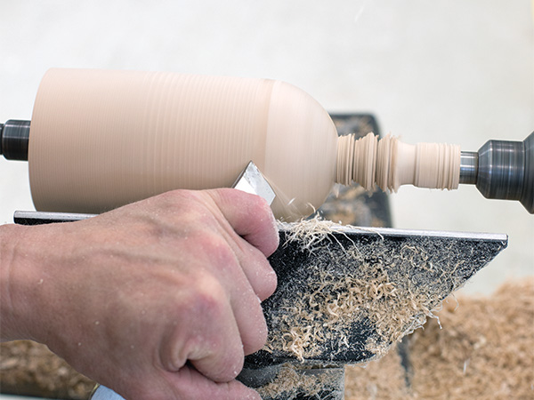
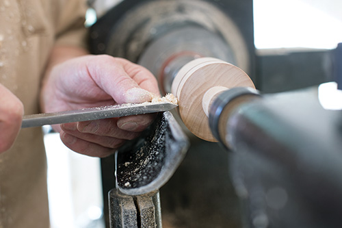
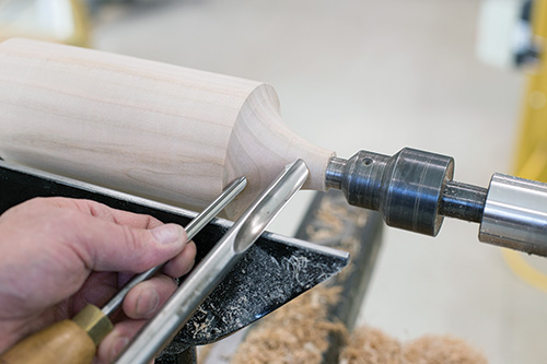
The photo shows typical bevel angles for these three commonly used tools. Bevel contact is important, but it should be light. Start the cut safely by gently touching the heel of the bevel on the wood and then lift and/or rotate the cutting edge into the wood to pick up a shaving. As you advance the tool, pay attention to what happens if you pivot the bevel away from the wood and too far toward the cutting edge: the tool will dig into the wood and make a nasty backward spiral. If the tool is pivoted too far away from the cutting edge (toward the heel of the bevel), you will lose the shaving and get no cut.
Principle 4: Bevel Contact
The depth of cut is controlled by gliding the tool’s bevel on the wood just behind the cutting edge.
Application
One way to observe the application of this principle is to clamp a piece of wood in a vice and try making a controlled cut with a carving gouge without the bevel contacting the wood. In carving and in turning, the cut is controlled by positioning the bevel. We often hear the phrases “rubbing the bevel” or “riding the bevel,” but those references can be misleading because they imply the use of a lot of pressure. Excess pressure of the tool’s bevel can burnish, bruise, or even crush the wood. It is better to imagine the bevel “gliding” or “skating” on the surface.
Bevel contact is important, but it should be light. Start the cut safely by gently touching the heel of the bevel on the wood and then lift and/or rotate the cutting edge into the wood to pick up a shaving. As you advance the tool, pay attention to what happens if you pivot the bevel away from the wood and too far toward the cutting edge: the tool will dig into the wood and make a nasty backward spiral. If the tool is pivoted too far away from the cutting edge (toward the heel of the bevel), you will lose the shaving and get no cut.
Keep in mind that the last part of the tool to contact the wood as the cut is made is the bevel. A long bevel with an abrupt transition between the bevel and the shaft of the tool will easily bruise the wood while making concave cuts. This can be remedied by grinding additional bevels to round over the heel and soften this transition.
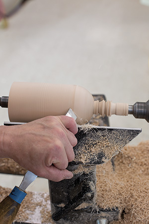
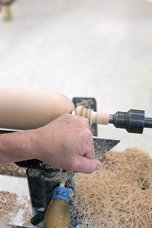
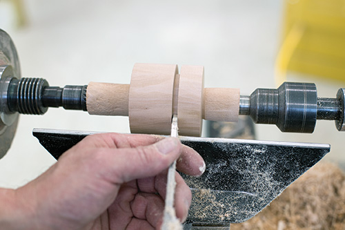
Principal 5: Cutting Arcs
When making curved cuts such as beads and coves, it is necessary to move the tool in three controlled and coordinated arcs to maintain bevel support, control the depth of cut, and create a smooth curve. These three arcs, which determine the approach angle of the tool, are discussed below.
Applications
Vertical arc
When cutting a bead, the tool handle will begin low and will be raised as the cutting edge approaches the end of the cut. When cutting a cove, this principle is applied in reverse: the tool handle will be higher at the beginning of the cut and will be lowered toward the end of the cut. So vertical arc refers to lifting or lowering the tool handle, depending on the type of cut you are making.
Horizontal/lateral arc
Horizontal, or lateral, arc refers to the movement of the tool handle from right to left or from left to right. When cutting a bead with a skew, the tool handle will begin at an angel of 45° to 60° to the wood and at the end of the cut will be closer to 90°. When cutting the right half of a bead, the tool swings from left to right. The same lateral motion is at play when cutting the right half of a cove.
Rotational/rolling arc
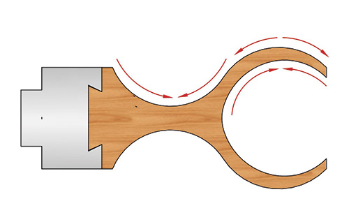
When cutting the right half of a bead with a spindle gouge, the flute starts near the 12 o’clock, or fully open position, and is rotated nearly to the 3 o’clock position by the end of the cut. For the left side of a bead the flute will end near the 9 o’clock position. When cutting a cove, the same principle is applied but in reverse. The flute will start facing the 9 or 3 o’clock position at the top of the cove and be rotated toward the 12 o’clock position at the end of the cut in the bottom of the cove. The rotation of the flute position is achieved by twisting the tool handle either clockwise or counterclockwise.
The tool movement shown in the progression shows all three cutting arcs: vertical, lateral, and rotational. The real challenge here is to control all three arcs simultaneously while turning beads and coves. This takes a lot of practice. While you are working on developing this skill, try to be aware of the motion needed to make the three arcs first independently and then coordinated into one smooth motion.
Note that moving the tool in these arcs is also required when sharpening spindle and bowl gouges. Each of these three arcs can be seen readily by watching the tool handle while grinding a gouge with the assistance of a sharpening jig.
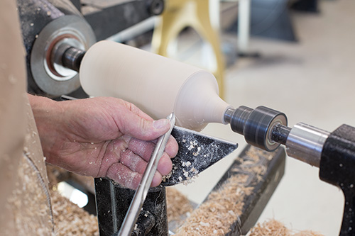
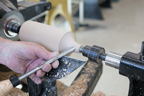
Principle 6 – Shavings
There are two related principles pertaining to the shavings that come off the wood:
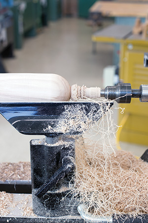
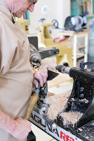
1. The quality of the cut is directly related to how little the shavings have to change direction as they leave the workpiece. Notice the difference in the path of the shavings when making a shearing cut as opposed to a scraping cut. With a scraping cut, the shavings have to change direction about 90 degrees as they are separated from the wood. This typically results in shavings that are crushed and broken and a surface that is somewhat torn. With a shearing cut, the angle at which the shavings leave the wood is reduced dramatically. These shavings usually come off the wood as long curls, leaving a cleaner cut with little or no torn grain.
2. Shavings must have a clear exit path. Examples of how common tools are designed to facilitate the removal of shavings include gullets in front of saw teeth, flutes in drill bits, and the window in a hollow-chisel mortising bit.
Applications
Direction of exit path
Experiment to see how changing the tool’s approach angle from 90° to 30° or 45° impacts both the quality of the shaving and the cut.
Clearance of shavings
Clearing the shavings is particularly important when forming V-grooves with a skew. A V-groove can be made with one pass of a skew, but this results only in the wood fibers being severed and pushed to the side, with no wood being removed. The fibers on the shoulders of the cut will be crushed and will not take a finish properly. A minimum of three cuts is required to produce a clean V-groove. The first pass cuts the fibers and pushes them aside, making room for the shavings to exit on subsequent cuts, which deepen and widen the V-groove. Also, cutting V-grooves before cutting a bead allows for removal of shavings and clearance for the tool as the bead cuts are made.
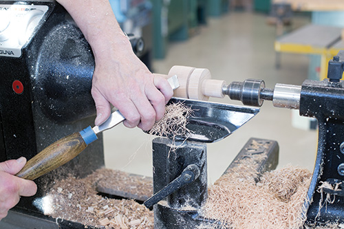
Principle 7: Tool Clearance
There must be clearance for the cutting tool to prevent friction and binding. This clearance (also called “set”) is designed into a saw blade by making the teeth cut wider than the body of the blade so the saw doesn’t bind in the cut.
Application
In woodturning, tool clearance is particularly important when making deep cuts with a parting tool. Most parting tools are not designed with a tip that cuts wider than the body of the tool. As a result, deep parting-tool cuts require that successive cuts be made to keep the cut wider than the tool itself. When making deep parting-tool cuts, cut only until you feel some extra resistance, then back the tool out and begin a new pass to slightly widen the cut. Continue repeating this process until the desired depth of cut is reached. This principle comes into play in obvious fashion when coring out nested bowls.
Principle 8: Amount of Cutting Edge Applied
Cuts that produce narrow shavings, with less of the cutting edge contacting the wood, produce finer surfaces. Smaller cuts put less stress on both the wood and on the tool. Examples of this can be seen in scissors and paper cutters. By not having the full cutting edge contact the material at one time, there is less pressure being applied, resulting in a cleaner cut. In woodworking, consider the cleaner surface produced by a helical-head planer than by a planer or jointer with straight knives, the length of which contacts the wood all at the same time.
Application
The application of this principle is straightforward. Consider the width of shaving when making scraping cuts. If you apply only a small part of a round-nose scraper, a cleaner cut will result. Conversely, if you apply the full width of a square-nose scraper, the resulting surface will be rougher and the tool may even dig into the wood. Experiment with changing the width of the shaving.
Principle 9: Feed Rate
The faster the feed rate, the rougher the cut will be. In general woodworking, “feed rate” refers to the speed at which the wood is passed through a cutter (or series of cutters). In woodturning, “feed rate” refers to the speed at which you advance the cutting tool. This principle applies to tool feed both on the X axis (parallel with the lathe bed) and on the Y axis (perpendicular to the lathe bed).
Application
A fast feed rate along the X axis impacts the spacing of the tool marks. When the edge of a board is passed too quickly over jointer knives, a series of peaks and valleys is produced, rather than a smooth, continuous cut. This is true in woodturning, as well. Moving the tool quickly along the X axis produces a shallow, spiral groove. This is not a problem when roughing, but a slower feed rate is needed to make a finishing cut that produces a smooth surface.
A fast feed rate on the Y axis impacts the thickness (and width) of the shavings. A fast cut toward the center of a spindle equates to a heavy cut, leaving a rougher surface than would a slower, lighter cut. This principle is closely related to Principle 8. Watch an experienced turner and notice how both aggressive and slow feed rates are used to the turner’s advantage. Roughing cuts can be made with aggressive feed rates, but finishing cuts are best made with slower, lighter cuts with a freshly sharpened tool. This approach can save a lot of time sanding.
It should be noted that the quality of cut is a factor not only of the feed rate, but also of the surface speed of the material. The surface speed, or the rate at which the wood is moving past the tool, is determined by your lathe’s rpm setting in relation to the diameter of the stock where the cut is being made. If the lathe is running quickly, say 3000 rpm, you can feed the tool more quickly than if the lathe is running at only 500 rpm. The key is to strive for the right feed rate (done by feel, since woodturning is controlled by hand) based on lathe speed, the diameter of the stock, and the nature of the cut (roughing or finishing).
Principle 10: Tool Stability
Holding a cutting tool stable during a cut will produce finer results with less vibration.
Application
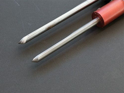
There are two factors that commonly impact the stability of the tool. One is the amount of metal in the tool (thickness), and the other is the distance of the toolrest from the tip of the tool (amount of overhang). You will notice a big difference between the stability of a 1/4″ (6mm) spindle gouge and a 1/2″ (13mm) spindle gouge. The smaller tool is good for cutting fine detail but must have toolrest support very near the cutting edge to prevent vibration. The larger tool has a greater capability to cut cleanly when there is more overhang over the toolrest. However, the 1/2″ gouge may be too large to cut small beads and coves. A 3/8″ (10mm) spindle gouge is a good compromise and consequently is the most commonly used spindle gouge.
I feel fortunate to have been introduced by Del Stubbs to the concept of basic principles that apply to cutting material. I have found that when I am getting poor results in turning, I can usually improve the quality of my cuts—and have a more satisfying experience—by reviewing these principles. I hope that they will be as useful for you as they have been for me.
All photos by Stephanie Staples.
Kip Christensen teaches wood prototyping, furniture design, and manufacturing at Brigham Young University. He has particular interest in woodturning education and has authored several articles and DVDs to help others learn the techniques of turning.