Back before you could buy one of those fancy and expensive pasta machines for your home, cooks used a simple set of specialty rolling pins for the same purpose. A traditional smooth-bodied roller was used for rolling out the dough, then rollers with various sized grooves were rolled through the flattened dough, cutting it into strips that became pasta! For this project, I decided to create a roller core that can share three or more sleeves. One is for rolling, and the rest are for forming the various sized strips of pasta.
Then, just as I got “rolling” on this project, my lathe decided to go on strike! Most of us would agree that woodworking is a proving ground of the old saying, “necessity is the mother of invention.” That is what drove me to create my rolling pin jig. I managed to mill the sleeves round, cut the grooves and even make the handles with a table saw, router and this new jig. In the next few pages, I’ll show you how it is done and, along the way, I’ll introduce you to the bird’s-mouth router bit and teach you how to make large diameter dowels on the router table.
Fashioning the Sleeve Blanks
Everything in this project is determined by the size of the rolling pin sleeves, so they need to be made first. Six segments (pieces 18) form a hexagon that gets milled round in the jig later. Mill your stock flat and straight. Remember that you are making three sleeves, so you need 18 pieces for your three-roller set. You will certainly want to make up a few extras for setups. My sleeves were to be 9-1/2″ long, so I cut 20 pieces a bit long — 10″.
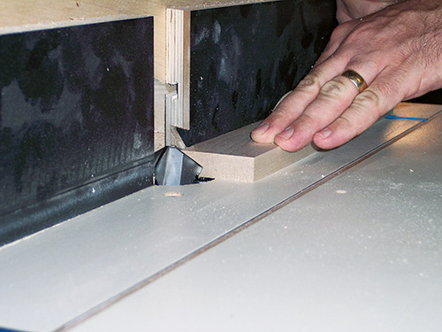
I set up the bird’s-mouth bit in the router table. Into one edge of the piece, this ingenious bit cuts an angled notch, which mates with the square end of the next, forming a 60° angle. Setting the bit is not difficult: the top part of the notch should be 5/8″ long (the same as the thickness of the end it mates with, as shown in the photos and illustrations). The peaks of the hexagon will get milled off, so the joint only needs to be close. Mill one long edge of each part, then dry-fit them together.
the glue dries.
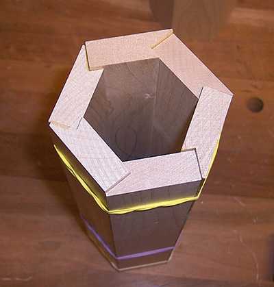
The width determines the overall diameter of the finished sleeve, which should end up just about 3″ at the smallest point. Spread glue into the notches and assemble them. For clamping, I used several rubber bands wrapped around the assembly. After they are done drying, trim off the ends, but leave them a bit long.
Creating the Core
The sleeves you just made will slip over a core that also holds the handles. Since the interiors of the sleeves are hexagonal, the core needs to be as well. It also needs a hole through the center to house one of the threaded rods (piece 19). Rather than try and drill a straight hole through the core, I made it in two parts (pieces 20), with a groove along the center of each.
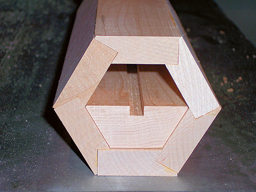
Carefully measure the inside of the sleeve along the widest point. That is the overall width of the core halves, with the thickness being half the small width of the sleeve. Mill the groove down the center of both halves. Then set the bevel angle on the saw to a 30° tilt, and bevel each long edge of the blanks. Test the fit inside the sleeve before gluing these pieces up, and be sure to err on the side of too large. Later, you can joint the faces of the core to adjust the fit.
Routing the HDPE End Caps
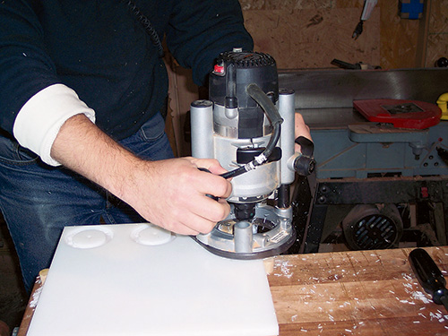
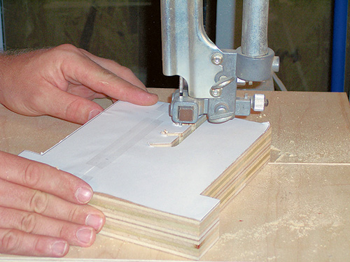
The end caps (pieces 21) keep the sleeves in place on the core. I milled them from 1/2″ HDPE (high density polyethylene). Inexpensive plastic cutting boards are a great source for this material. I drilled a 1/4″ pilot hole in the plastic, then used a router and trammel to cut a circular groove halfway through the plastic. The inner ring formed this way (bottom photo, right) was cut to fit close inside the sleeve. I then reset the trammel and cut their overall 2-7/8″ diameters.
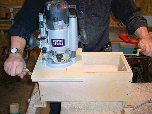
Assembling the Jig Box
The trick to milling the hexagonal sleeves round is a box-style jig. It holds the core and sleeve assembly so it can be turned underneath a router bit. On top of the box, a sliding plate guides the router back and forth along the length of the box. Although I only needed one point to turn the rolling pin under the router, I made the ends with slots at three levels so I could use the jig for other projects with different diameters (see Drawings). The ends (pieces 1) are cut to size and notched for the sides. To make the slots, I used a 1/4″ drill bit at the endpoints and I cut the slots at the band saw. I then cut the sides (pieces 2) to length. Assemble the jig with glue and screws, and add the clamping blocks (pieces 3).
Building the Router Slide
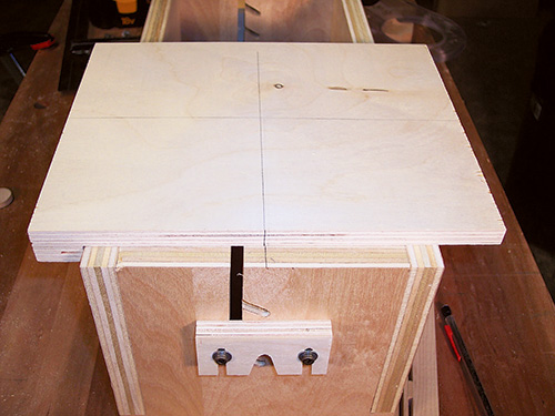
The router slides across the top of the jig box on a custom base. It needs to slide easily but be snug enough to not shift, spoiling the grooves during milling. I used 1/2″ Baltic birch for the base and attached a fixed fence to one side (pieces 4 and 5). To keep it snug, I attached a spring-loaded fence (piece 6) to the other side of the base. It consists of a base part with offset spacers and face strips to provide a stiff spring action, keeping the slide tracking smoothly (see Drawings).
To be sure that the router is properly centered, I mounted the slide on the jig box and transferred the center lines. Then I drilled the mounting holes and through hole for the router. Bore the through hole large enough so you’ll be able to see your work.
Adding the Indexing System
Rounding the hexagonal sleeve is smoother and easier with the router drawn fluidly along the length of the jig. Cutting evenly spaced grooves on the other two sleeves is impossible without an accurate indexing system. Both of these are accomplished using a threaded rod system mounted to the outside of the jig (see Drawings).
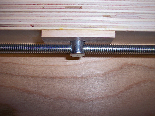
Fix one of the rods (piece 7) to the jig side with steel angle brackets (pieces 8). The outer hole in the bracket is drilled out to 1/4″. Set jamb nuts and washers (pieces 9 and 10) to either side of the bracket so that the threaded rod does not slide side to side. Add a cross dowel (piece 11) between the brackets to connect the slide to the indexing rod, and fabricate the small crank (pieces 12, 13 and 14) for the end. Use two nuts tightened against one another anywhere the nuts must stay tight.
Drill a hole into the bottom of the cross dowel bracket (piece 15) of the slide plate. The cross dowel fits into this hole, allowing the indexing system to move the slide back and forth.
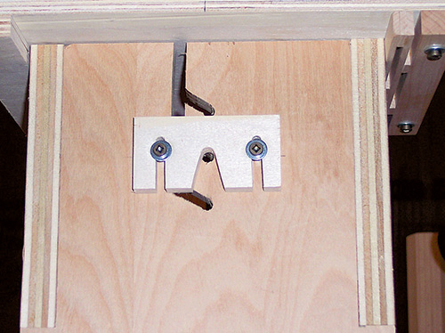
The last pieces of the jig to add are a pair of locking cleats (pieces 16). The assembly will be mounted on a threaded rod resting in one of the slots at the ends of the jig box. You’ll fix these locking cleats in place on the jig with pairs of hex head wood screws and washers, to trap the rod in its slots.
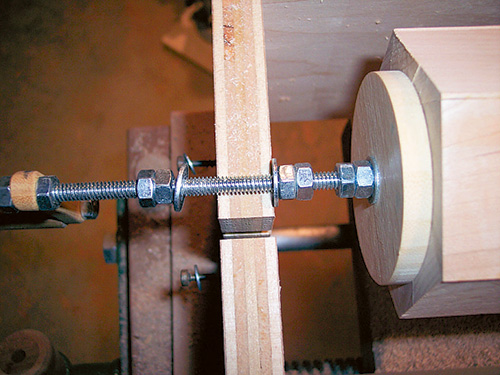
Mounting the Rolling Pin
The second piece of threaded rod, along with two sleeve clamp discs (pieces 17), jamb nuts and washers are used to hold the rolling pin assembly in the jig for milling. Another crank handle assembly is attached to one end, then sets of jamb nuts and washers are placed at each side of the jig box ends to keep the assembly from moving back and forth. Set the rolling pin in the center of the jig box with the clamp discs and jamb nuts and tighten to keep the assembly from slipping on the threaded rod as you move on to turning it.
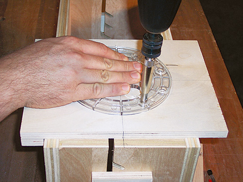
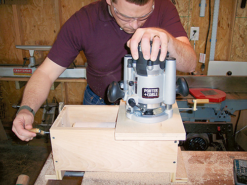
Rounding the Sleeves
For rounding, a standard straight cutter can be used, but there are better choices. A round-nose (or core box) bit cuts more smoothly, since the rounded end takes a shallow cut at the edge and deeper toward the center. This really reduces the possibility of tearout. Because of its round tip, the core box bit needs to be moved in small increments to leave a smooth surface behind. The best bit is a dish carving bit. It has the same smooth cutting properties as the core box, but a wide flat in the center means that the cuts overlap, leaving a very smooth finish.
With the rolling pin mounted in the jig, and the router mounted on the slide base, turn the indexing handle until the router is off the end of the sleeve. Plunge the router down and lock it. Only take a shallow cut at first. With the router running, begin slowly turning the rolling pin assembly and the indexing handle at the same time. The router will begin shaving the high spots off the hexagonal sleeve. Do not let go of the rolling pin handle, or the rotating bit will tend to spin it fairly rapidly! Keep moving the slide across the jig evenly until you reach the other end. Then lower the bit and mill back across. Continue this process just until the sleeve is round.
Cutting the Grooves
Obviously, one of the sleeves will be left as a smooth cylinder. The other two get grooved, and the indexing system allows you to cut evenly spaced grooves. The threaded rod has 20 threads per inch, so each full turn of the rod moves the router bit by 0.05″. For the narrow strips, we want 1/4″ grooves spaced 1/8″ apart. So center to center, the bit needs to move 3/8″, or 0.375″. That means 7-1/2 turns per groove. In order to ensure even ends, mark the center of the sleeve length, and start there. With the router unplugged, plunge the bit down to the surface of the sleeve.
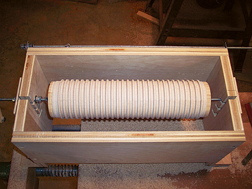
Now set the depth stop to 1/8″ deep. With the router running, plunge it down slowly as you turn the rolling pin assembly. Be sure to turn the assembly so that the groove is an even depth all the way around. With the center groove done, move the bit over by turning the indexing handle 7-1/2 turns, and start the next groove. Work from the center to one end, then return to the center and work across the other half.
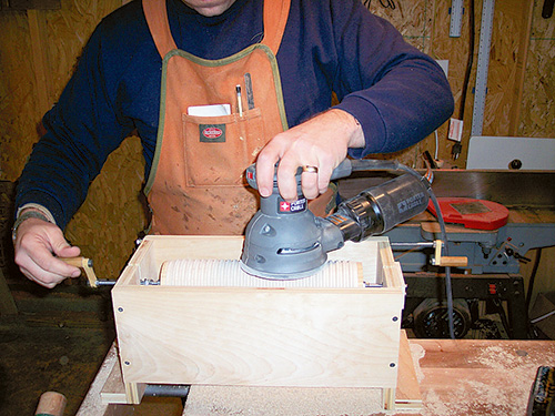
The last sleeve is grooved wider, but the process is the same. I used a 1/2″ round-nosed bit and cut no more than 3/16″ deep. Center to center, these grooves should be 5/8″ apart, or 0.625″. This works out to 12-1/2 turns. (In either case, you can actually just do eight or 13 turns and ignore the half, since you will be trimming the ends of the sleeves later, making the grooves even. You can use a small sander to smooth the sleeves while they’re still in the jig.
Shaping the Handles
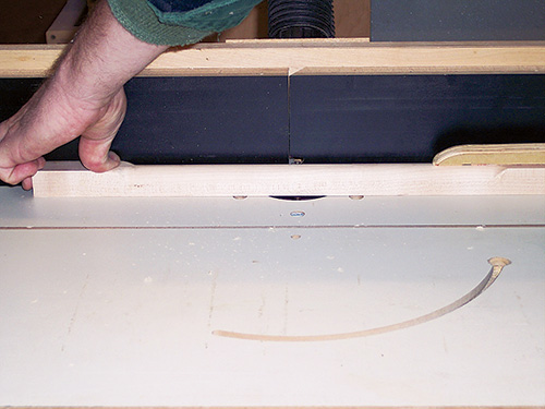
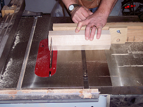
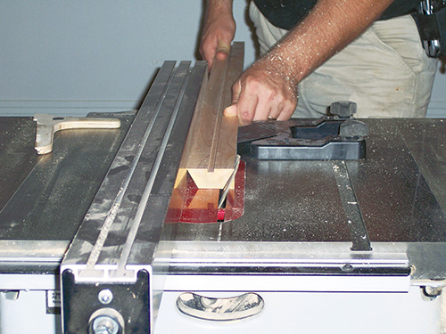
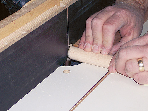
The last parts to make are the handles (pieces 22). You may be able to find handles at a craft store, or you can buy 3/4″ or 1″ dowels. I chose to make my own in the shop. I started with a 1″ x 1″ piece of stock and installed a 1/2″ roundover bit in the router table. For safety, I made the stick several inches longer than needed. Leave the ends square and rout the center section only, rounding over all four long edges. Cut the handles 5″ long, then round their ends. I used the same setup to do this, but I moved the fence in a little and added a block to rest the handle against as I rolled the end over the bit. Then I drilled a 1/4″ hole three inches in to each handle, followed by a 1/2″ counterbore deep enough to house two jamb nuts (pieces 23).
I finished all of the wood parts with three coats of salad bowl finish, lightly sanding between coats. Wax the core to ensure that the sleeves will slide smoothly on and off.
Final Project Assembly
Trim your three sleeves to final length. Mine were 9-1/2″, but it can vary a bit to even out your grooves. All three do need to be the same length. Cut the core section 1/2″ shorter, to account for the step in the end caps. Now cut the threaded rod to length (add up the sleeve plus the endcaps, plus three inches for each handle. (In my case, this was 16 inches overall.)
Now thread two nuts onto one end of the threaded rod, about 3″ in from the end, and jam them together there. Use epoxy to glue this end of the rod into one of the handles. Wax another scrap of threaded rod, turn two nuts onto it, and epoxy them into the other handle. As the epoxy begins to harden, carefully unscrew the threaded rod from the second handle, leaving the nuts behind, glued in place in the handle. You now have one handle with 13 inches of threaded rod in it, and another with just the nuts embedded in it.
To assemble the rolling pin, slide one end cap down the threaded rod, then the core, one of the sleeves and the other end cap. Thread on the other handle. To change sleeves, simply disassemble the parts, slip the new sleeve in place and replace the endcap and handle.
Use the smooth sleeve to roll out the pasta, then switch to one of the grooved sleeves
to cut the pasta into strips. Bon Appetit!